
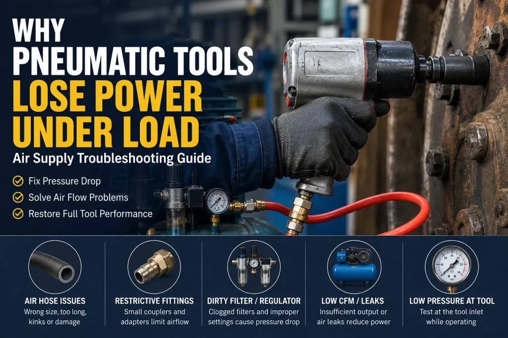
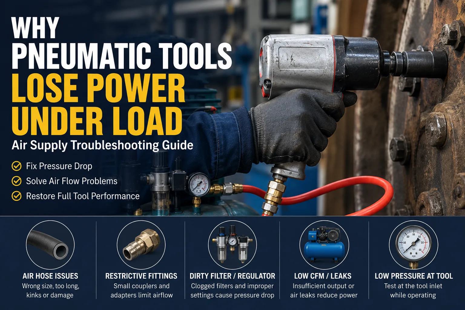
When a pneumatic tool loses power under load, the tool itself may not be defective. An undersized hose, excessive length, restrictive fittings, a clogged filter, leakage, or insufficient compressor output can all reduce pressure and airflow at the tool. Test the system while air is flowing, locate the restriction, and replace only the component that fails the test.
| Symptom | Inspect first | First check |
| Runs freely but stalls under load | Tool-end pressure and airflow | Measure inlet pressure while operating |
| Starts strong, then fades | Compressor recovery or flow restriction | Watch pressure during continuous use |
| Only one station is weak | Local hose, couplers, regulator, or filter | Compare with a working station |
| Every station is weak | Compressor, main filter, piping, or leaks | Compare several system points |
| One tool is weak everywhere | Lubrication or internal wear | Test another tool on the same supply |
A tool may initially run from stored air and weaken when the system cannot maintain flow. This is common with grinders, sanders, drills, and repeated impact-wrench use. If receiver and branch pressure fall together, compressor recovery or simultaneous demand may be responsible. If upstream pressure stays stable while pressure at the tool falls, inspect the hose, reel, fittings, and air-treatment components.
Shorten the hose, remove unnecessary connectors, and run one tool at a time before specifying new equipment. These checks help distinguish insufficient compressor CFM from air hose pressure drop or a local restriction.
If only one workstation performs poorly, inspect components unique to that branch and test the same tool at a nearby station. If every station is weak, compare receiver, main-line, and point-of-use pressure.
U.S. Department of Energy guidance identifies hoses, quick disconnects, filters, regulators, and lubricators as common point-of-use pressure-drop sources. Broader problems can include leaks, distribution restrictions, or inadequate supply.
Static pressure is measured when little or no air is moving. An undersized hose or restrictive coupler may therefore show little pressure difference. Dynamic pressure is measured while the tool consumes air, when restrictions become visible.
This explains why an air tool can feel weak even when a compressor gauge shows 90 PSI. The gauge may be upstream from the restriction, and the tool also needs sufficient airflow at its specified pressure. A normal static reading does not confirm adequate air under load.
An impact wrench that runs freely but cannot loosen a fastener, or a grinder that slows after contact with the workpiece, may be experiencing inadequate dynamic pressure rather than low static pressure.
Install a suitable pressure gauge close to the tool inlet. Run the tool under a representative load and compare the reading with the tool manufacturer’s requirement. Then move the test point upstream—before the hose, reel, regulator, and filter. A significant difference between two points identifies the section needing inspection.
DOE guidance recommends measurements at multiple locations rather than assuming the compressor is at fault. Testing should be handled by personnel familiar with compressed-air hazards. OSHA also states that visibly damaged or unsafe compressed-air hose must not be used in covered maritime work.
A hose may connect correctly but still have insufficient internal diameter for the tool’s airflow demand. High-consumption impact wrenches, grinders, sanders, and drills are more likely to expose this restriction.
Check the actual hose ID rather than the outside diameter or fitting thread. Compare performance with a shorter, serviceable hose or a larger-bore assembly. If dynamic pressure and output improve, the existing hose or its end connections are limiting flow.
Replacement selection should consider:
A larger outside diameter does not necessarily mean a larger airflow path.
Longer flow paths create more resistance, especially when the bore is small relative to demand. Tight bends, permanent kinks, small reel drums, reducers, whip hoses, and multiple quick-connect sets add restrictions.
Straighten the hose, safely bypass the reel, remove unnecessary extensions, and repeat the test. Replace hose with leaks, permanent deformation, exposed reinforcement, soft spots, or unsafe cover damage. OSHA states that visibly damaged compressed-air hose should not be used.
Increasing compressor pressure is not a substitute for correcting an undersized or damaged assembly. It may leave the bottleneck in place while increasing pressure elsewhere in the system.
Two fittings with the same nominal thread can have different body sizes, plug profiles, internal bores, valves, and flow characteristics. The smallest passage can limit the workstation.
For high-CFM tools, check the coupler series, mating plug, thread standard, internal bore, and available flow data. Avoid unnecessary reducers and confirm that every connection from the branch outlet to the tool inlet can support demand.
This is particularly important when a large impact wrench is connected through fittings originally selected for a small assembly tool. A fitting that physically connects is not automatically suitable for the required airflow.
A clogged filter may reduce airflow, while an undersized regulator can hold its setting with the tool off and lose outlet pressure when demand rises. Lubricators, valves, and manifolds can add smaller losses that become significant together.
Measure pressure before and after each component while the tool operates. A large differential may indicate:
DOE guidance identifies filters, regulators, lubricators, disconnects, and hoses as common locations for excessive point-of-use pressure drop.
If receiver pressure falls rapidly when the tool runs, or performance drops only when several stations operate together, review compressor output, leaks, storage, and simultaneous demand. Run the weak tool alone and compare receiver pressure with tool-inlet pressure.
If dynamic inlet pressure meets the tool requirement but performance remains poor, inspect lubrication, moisture, contamination, seals, bearings, vanes, or impact parts. Test the suspect tool at a working station, then connect a serviceable tool to the original supply.
This two-way comparison separates an air-supply problem from a tool defect and prevents unnecessary hose replacement. Maintenance should follow the tool manufacturer’s instructions because lubrication and air-quality requirements may vary by tool design.
Record dynamic pressure at critical stations after the system operates correctly. This creates a reference point for future troubleshooting. Inspect hoses for leaks, kinks, abrasion, hardening, soft spots, and coupling damage. Replace filters according to their condition and supplier guidance, and avoid repeatedly adding adapters or extension hoses.
For high-consumption tools, standardize the approved hose ID, practical maximum length, coupler series, and FRL capacity. Review simultaneous demand before adding another workstation or operating several continuous-air tools on the same branch.
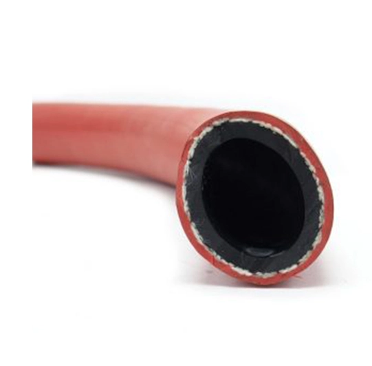
A replacement air hose RFQ should include:
For industrial air service, compressor lines, and pneumatic tools where oil resistance is required, SOMAXFLEX lists an industrial air hose for pneumatic tools with a black nitrile tube, synthetic-yarn reinforcement, red NBR-blend cover, a 300 PSI working-pressure rating, and multiple IDs. Suitability should be verified against the complete application, including airflow, temperature, fittings, and working environment.
After confirming bore, pressure, construction, and environment, buyers can compare options in the industrial air hose range.
A supplier should ask about airflow, tool-inlet pressure, hose length, duty cycle, fittings, and operating conditions before recommending a product. Documentation should distinguish ID from OD, working pressure from burst pressure, and inner tube from reinforcement and cover.
Der SOMAXFLEX industrial hose website organizes products by medium and application. The SOMAXFLEX company profile describes its focus on industrial rubber hoses, including compressor air, steel-wire air, and multi-purpose hose categories.
For bulk or customized sourcing, compare specification compliance, samples where appropriate, dimensional requirements, marking, packaging, documentation, and commercial terms. A recommendation should be tied to operating data rather than general claims such as “high flow” or “heavy duty.”
When pneumatic tools lose power under load, test dynamic pressure at the tool and move upstream one section at a time. Separate hose restrictions from compressor and tool problems before buying replacement parts.
For an application review, submit the tool model, air consumption, required pressure, hose ID, length, fittings, operating environment, target quantity, and available failure photos through request an air hose specification review.
Q1: Why are my air tools weak even when the compressor shows 90 PSI?
A: The gauge may show static or upstream pressure. A restrictive hose, coupler, filter, or regulator can reduce pressure only while air flows. Measure inlet pressure while the tool operates.
Q2: How do I know whether my compressor has enough CFM?
A: Run the tool alone and compare receiver pressure with tool-inlet pressure. Falling receiver pressure suggests a supply, leakage, storage, or demand problem. Stable receiver pressure with low tool pressure suggests a downstream restriction.
Q3: Can a small quick-connect coupler reduce impact-wrench power?
A: Yes. A small internal passage can restrict airflow even when the thread fits. Compare coupler bore, plug profile, flow data, and dynamic pressure across the connection.
Q4: Does a longer air hose reduce pneumatic-tool performance?
A: It can. The effect depends on hose ID, airflow demand, length, fittings, bends, and reel design. Compare the system with a shorter or larger-bore hose under load.
Q5: When should an industrial air hose be replaced?
A: Replace a hose that leaks, remains permanently kinked, shows unsafe damage, exposes reinforcement, or cannot deliver the required airflow after fittings and routing are corrected.